LED (Red/Green)
Overview
Age Range: First time using external devices for the micro:bit
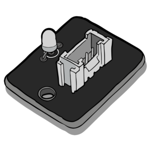
In this lesson students will learn how to program the micro:bit to control an external bi colour LED. Bi colour means the LED has 2 colour options that be programmed. In this case red and green.
The lesson activity will build up from turning on the LED to using both colour options available.
Aims
- Learn how to program an external component using the micro:bit.
Download the Code
MakeCode Editor
Click the button below to download the MakeCode editor code for this lesson. The hex file is contained in a zip folder.
Kindly refer to our download the code page for instructions on how to upload your code onto the micro:bit. Please use instructions set A.
This code can also be uploaded into the MakeCode editor.
Activity 1
Activity 2
Kit Required
Micro:bit

Mini Innovation Board

LED (Red/Green)

- MicroUSB Cable
- 1 x Connector Cable
Preparation
- Connect the micro:bit to the Mini Innovation board via the edge connector.
- Use the connector cable to connect the LED to the ADC1 connector on the Mini Innovation board.
- Connect the micro:bit to a computer via the microUSB cable.
- Go to the MakeCode website on your computer and open a new project.
Time to Code
As you go through these steps please note that there are images of the completed code to the right.
Activity 1
- To begin, students will simply be turning one of the LED colours on.
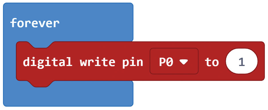
- Select the ‘forever’ block from the ‘basic’ tab. On new projects this may already be on the screen.
- Next choose the ‘digital write pin’ from the ‘pins’ tab. The ‘pins’ tab can be found in the ‘advanced’ section. Insert this block into the ‘forever’ block.
- The ADC1 connector on the Mini Innovation Board connects to P0 and P3 on the micro:bit. These can be selected from the drop down in the ‘digital write pin’ block. For this activity select P0 from the drop down. This may already be chosen.
- A digital signal is either on(high) or off(low). This is represented by 0 and 1. 0 being off(low) and 1 being on(high). Change the state on the ‘digital write pin’ to 1. This will turn the LED on.
- The code is now finished! Download the code and upload it onto the micro:bit. The instructions for this can be found on the download the code page. Please use instructions set B.

Activity 2
- This activity will build on activity 1 where one LED colour was turned on. This time students will alternate between the colour options having a different colour turned on for 2 seconds at a time.
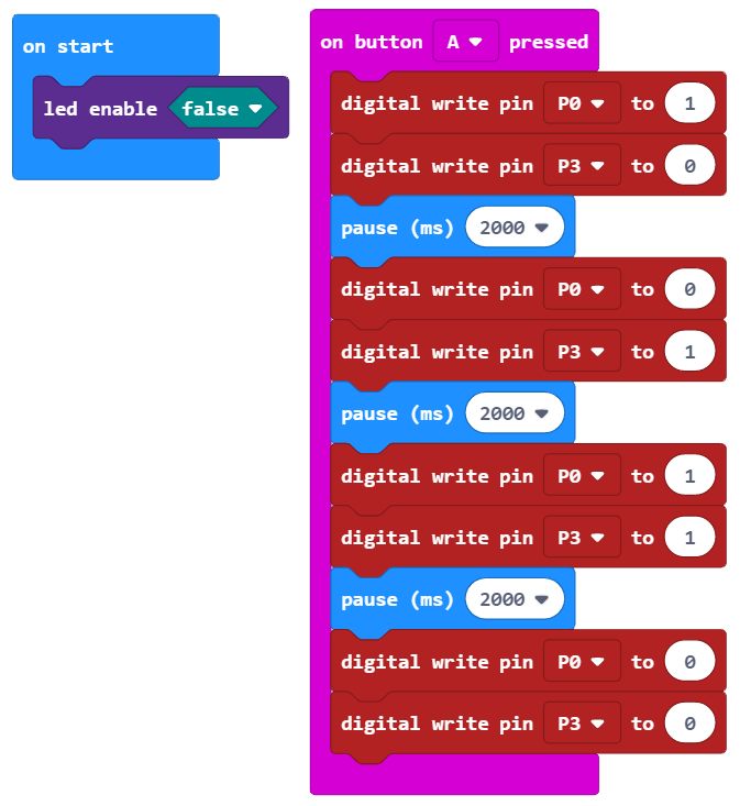
- Begin by selecting the ‘on start’ block from the ‘basic’ tab and the ‘on button pressed’ block from the ‘input’ tab. Choose button A from the ‘on button pressed’ dropdown.
- Next, select the ‘led enable’ block from the ‘LED’ tab and insert it into the ‘on start’ block. This block disables the LED matrix on the micro:bit. The reason for this, is when P3 is used it interferes with the LED matrix. Students will use P3 in this activity.
- Select the ‘digital write pin’ block from the ‘pins’ tab and insert it into the ‘on button pressed’ block. Select P0 from the drop down and set the state to 1. Select another ‘digital write pin’ block and attach it to the bottom of the previous block. Choose P3 and set the state to 0.
- Select the ‘digital write pin’ block from the ‘pins’ tab and insert it into the ‘on button pressed’ block. Select P0 from the drop down and set the state to 1. Select another ‘digital write pin’ block and attach it to the bottom of the previous block. Choose P3 and set the state to 0.
- So far the the code will turn on one of the LED colours when button A is pressed.
- Next, students need to duplicate the 3 blocks within the ‘on button pressed’ block 3 more times. Attach these into the ‘on button pressed’ block as seen in the code image.
- To turn on the other LED colour set P0 state to 0 and P3 state to 1. To mix the colours set the state of both P0 and P3 to 1.
- Finally students need to turn the LED off. To do this set states of P0 and P3 to 0.
- The code is now finished! Download the code and upload it onto the micro:bit. The instructions for this can be found on the download the code page. Please use instructions set B.

What Will Happen
When button A is pressed one of the LED colours will turn on for 2 seconds. Next, the other colour will turn on for 2 seconds. After that both colours are turned on and mix to create another colour. This will happen for 2 seconds. Finally the LED will turn off and wait for button A to be pressed again.
Taking it Further
- Create a light sequence using the colour options available on the LED.
- Use the skills learned to help complete the more advanced control lessons.
Keep in touch
We would love to keep you up to date with all of our latest news, offers and new products.
If you would like to subscribe to our mailing list please click the button below.
Contact Us

ScienceScope Limited
Downside School
Stratton-on-the-Fosse
Radstock
BA3 4RJ
enquiries@sciencescope.uk
